A conveyor system trial run is your first full‑system proof that the mechanical build, electrics, controls, and safety measures work together as intended. This field guide walks you through a practical, safety‑first process for fixed belt conveyors—from pre‑start checks to staged loading and documentation. Follow your OEM manuals and site procedures first; the steps below complement them. For safety and compliance anchors, see OSHA’s Lockout/Tagout standard (1910.147), machine guarding requirements (Subpart O), MSHA safety alerts for mining contexts, EN ISO 13850 on emergency stop principles, and IEC 60204‑1 for electrical equipment of machines. Links are provided inline where referenced.
Safety prerequisites and regulatory anchors
Before any power is applied, confirm that everyone understands and follows the local procedure for isolating energy and verifying zero energy state. OSHA’s Lockout/Tagout program lays out the sequence—notify, shutdown, isolate, apply locks/tags, verify isolation, and later restore—see the official text and example procedure in OSHA’s Lockout/Tagout standard 1910.147. Guards for rotating parts, pulleys, and in‑running nip points must be in place per OSHA’s Subpart O machine guarding requirements (commonly 1910.212/219).
- Reference: Review the official Lockout/Tagout requirements in OSHA’s 1910.147 standard via the detailed regulation page: OSHA 1910.147 Lockout/Tagout.
- Reference: For guarding of pulleys, belts, and rotating parts, see the consolidated machine‑guarding section: OSHA 1910 Subpart O — Machinery and Machine Guarding.
If you are in mining operations, MSHA reiterates the hazards of working near rotating rollers and pinch points and stresses LOTO before tracking or cleaning. Their safety alert is a succinct reminder: MSHA Rotating Conveyor Rollers Safety Alert (PDF).
Two international standards provide design and verification context: EN ISO 13850 frames emergency stop as a complementary protective function (not a substitute for guarding) and IEC 60204‑1 covers bonding/earthing, protection, control circuits, and E‑stop integration for machinery. See: EN ISO 13850 catalog page and IEC 60204‑1 catalog page.
Field note: Only qualified electricians should open energized enclosures or alter phasing. Never remove a guard without LOTO verified.
Pre‑start inspection checklist (field‑ready)
Use this sequence to catch issues before the first jog. Roles and PPE are site‑specific; at minimum, use hard hat, safety glasses, gloves, hi‑vis, and hearing protection.
- Structure and frame
- Check stringers and supports for squareness and cross‑level. Confirm anchor bolts are torqued. Verify walkways and handrails are secure and clear.
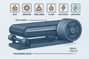
- Belt and splice acceptance
- Inspect splice: uniform thickness and alignment; no open rubber, broken cords, or loose fasteners. Confirm cure time (hot/cold vulcanization) met OEM guidance or fastener torque matches the supplier’s spec (documented).
- Idlers and pulleys
- Spin idlers; replace any seized or noisy units. Inspect pulley lagging; confirm there’s no delamination. Verify snub and tail pulleys are square to the centerline.
- Guards and interlocks
- Confirm all fixed guards at pulleys, drives, and nip points are installed and secure. Check access gates/interlocks function mechanically (closed/latched) prior to power‑on.
- Electrical and grounding
- Visually confirm bonding/earthing conductors, cable routing, and gland seals. Control stations labeled and legible. No obvious damage to conduits or junction boxes.
- Housekeeping and signage
- Remove tooling, debris, and packing materials. Post “commissioning in progress — keep clear” signs and set up barricades if needed.
- LOTO verification
- Identify all energy sources. Apply locks/tags per site procedure. Test for zero energy. Document who applied which lock and on what device.
If any item fails inspection, correct and re‑verify before proceeding.
Device‑by‑device functional checks (before continuous run)
Definitions you’ll use:
- Jog mode: a momentary, low‑risk way to inch equipment for checks.
- Permissive: a condition that must be TRUE before a start is allowed (e.g., guards closed).
- Interlock: a protective condition that forces a stop or prevents starts (e.g., E‑stop pulled).
Perform these checks methodically, with spotters and radios:
- Solo motor and rotation direction
- With guards confirmed installed and area clear, temporarily remove LOTO, energize controls, and jog the motor to confirm the correct rotation. If reversed, de‑energize, LOTO, and have an electrician correct phasing (swap any two phases on a three‑phase motor). Re‑install or confirm all guards.
- Gearbox/coupling observation
- During brief jogs, look for abnormal wobble, noise, or coupling guard interference. Stop immediately if observed.
- Controls dry‑check
- Verify each local/remote start/stop station behavior and selector switches (Local/Remote/Off) without commanding a full run. Confirm permissives and interlocks display correctly on the HMI or indicator lamps.
- Baseline readings
- Record nameplate ratings, no‑load current at first jogs, and ambient temperature. These become your baseline for extended runs.
No‑load trial run and logging cadence
Start with short jogs (10–50 meters) to confirm the belt tracks without rubbing. When stable, transition to a continuous, no‑load run. Station observers at the tail, head, and any transfer points. Maintain radio communication and a simple time‑stamped log.
Recommended observations during no‑load:
- Motor current every 5–10 minutes (compare to baseline)
- Drive, motor, and take‑up/bearing temperatures every ~10 minutes (watch for rapid rises)
- Tracking at key points every 5 minutes (belt should stay centered and clear of structure)
- Audible/visual checks for abnormal vibration or rubbing
Example log snippet you can replicate:
Time    Loc   Current(A)  Drive Temp(°C)  Tail Brg(°C)  Tracking Note
09:10   MCC   38          48              41            Centered; no rub
09:20   Tail  39          49              43            Drifts 10 mm right; hold
09:30   Head  39          51              45            Stable after idler tweak
Safety spot‑tests during no‑load: Test at least one emergency pull‑cord or E‑stop (in a controlled manner) to confirm the conveyor stops and restart logic works per your procedure. Verify the zero‑speed device trips correctly when rotation ceases (you’ll do a full test later). Keep guards installed throughout.
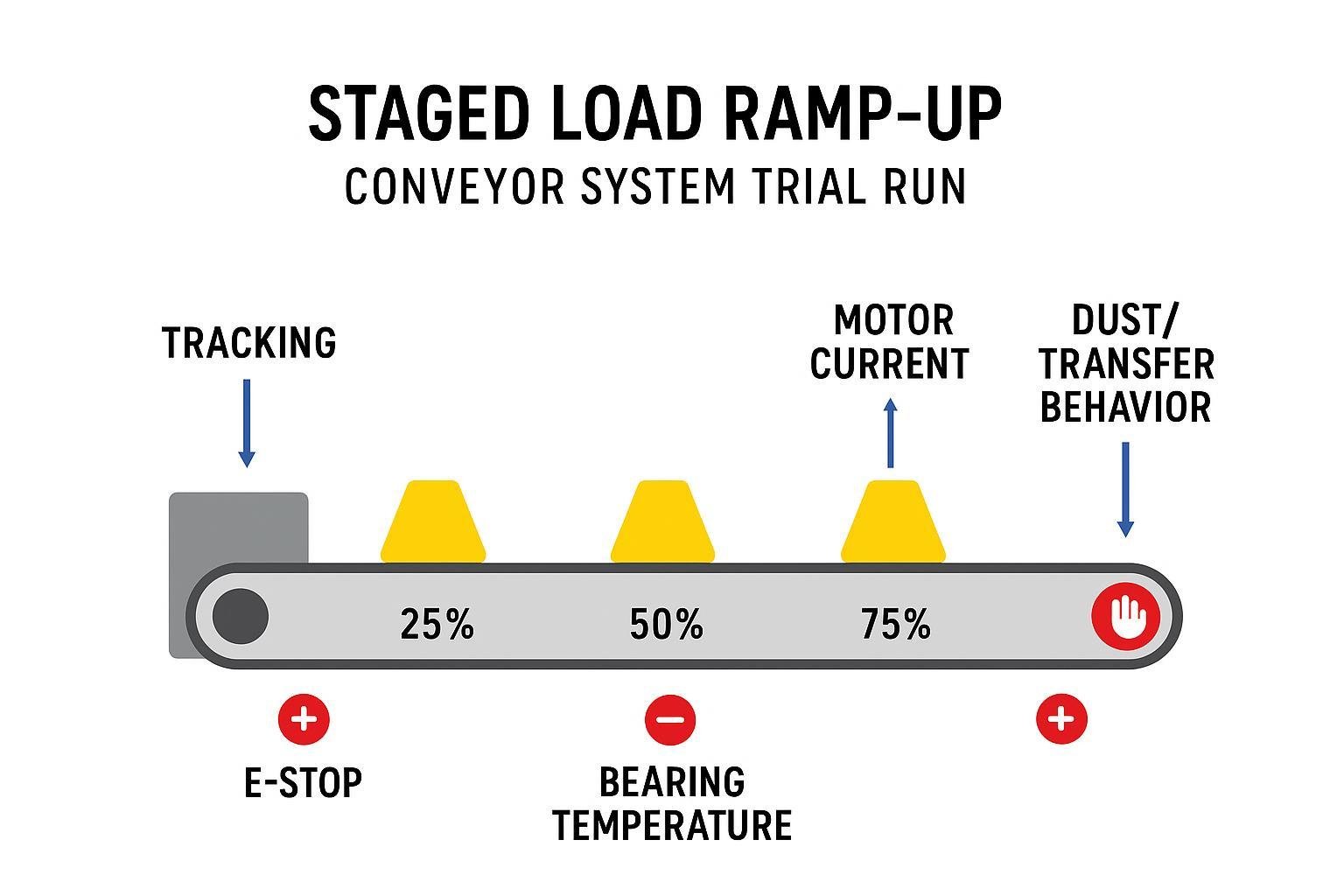
Staged load introduction and ramp‑up
Many sites adopt staged loading (for example, ~25% → 50% → 75% → 100% of design feed) to surface issues gradually. Treat the exact stages and dwell times as site/OEM‑defined. At each stage, monitor:
- Belt tracking stability and any tendency to climb into skirts or structure
- Drive slip, unusual current spikes, or alarming temperatures
- Transfer chute behavior: impact pattern, plugging, material containment, and dust
- Skirtboard and sealing performance; spillage or carryback signs
Hold or roll back a stage if you see persistent tracking drift, slipping, plugging, or abnormal heat/noise. Log what you changed (e.g., tensioning, idler tweak) and re‑observe before increasing load.
Alignment and belt tracking verification
Verify fundamentals first: frame straightness and cross‑level, then pulley alignment (especially tail and snub). Only after that make small, incremental adjustments to return‑run idlers to steer the belt. Change one variable at a time and document the adjustment and its effect. A belt is considered acceptable for commissioning purposes when it remains centered on idlers and pulleys over extended observation without contacting structure or chewing skirts.
Neutral example: Modern troughing idlers and return trackers from manufacturers such as BisonConvey can support stable tracking when frames are square and belt tensions are set per OEM guidance. The key is correct selection, installation, and incremental adjustment—not a brand label.
Tip: After each tweak, let the belt run long enough to see a steady‑state effect. Think of it like adjusting a steering trim—small moves, then watch.
Safety device verification and sequential logic tests
Define two devices upfront for clarity:
- Zero‑speed (underspeed) switch: a sensor/monitor pair that detects loss of rotation and trips an alarm or stop.
- Belt‑sway (misalignment) switch: a mechanical or proximity device mounted near the belt edge that trips when the belt wanders too far.
Test each safety function deliberately:
- Emergency stops and pull‑cords: Activate each one and verify the conveyor stops as designed, the alarm/indicator reports the correct zone, and reset/restart follows procedure. Spot‑test propagation if multiple conveyors are interlocked.
- Zero‑speed: Run under normal speed and confirm no nuisance trips. Command a stop and verify the device trips within its set delay and resets properly afterward.
- Belt‑sway: With the line running in a safe, controlled state, gently simulate a misalignment at the test station (per device manual) to confirm trip and reset behavior. Document position, set distance, and result.
For multi‑conveyor lines, verify sequence logic:
- Attempt to start a downstream conveyor with the upstream “run feedback” false—start should be inhibited.
- Start upstream, then confirm the permissive allows the downstream start.
- Command an orderly stop at the downstream unit and confirm upstream units stop as required by design.
Record which safety channel, input card, and logic block correspond to each device so maintenance can trace faults later.
Troubleshooting quick reference
Below is a compact table you can use during the conveyor system trial run. Adjust to your site’s devices and OEM limits.
| Symptom | Immediate safety action | Likely causes | Rapid checks | Corrective action |
|---|---|---|---|---|
| Belt drifts to one side | Keep people clear; prepare for controlled stop if rubbing | Frame not square; tail/snub misaligned; idlers out; uneven loading | Check frame straightness, tail/snub squareness; inspect return idlers | Correct alignment fundamentals; then small idler tweaks; re‑observe |
| Belt slips at drive | Stop if persistent; avoid glazing lagging | Low tension; wet/contaminated lagging; overload | Check take‑up force; inspect lagging; compare current vs. baseline | Adjust tension within OEM range; clean/replace lagging; reduce load and ramp |
| Bearing/motor overheating | Stop if temperatures climb rapidly | Seized idler; poor lubrication; misalignment; electrical issue | IR scan bearings; listen for noise; compare current draw | Replace seized idlers; correct alignment; have electrician test motor |
| Reversed rotation on jog | Keep area clear; stop immediately | Motor phasing reversed | Visual rotation check | LOTO; electrician to swap two phases; re‑test |
| Excessive dust/spillage | Limit personnel exposure | Poor skirt seals; chute impact pattern off | Observe transfer pattern; check skirt gaps | Adjust liners/skirt seals; tune feed and chute flow |
Documentation and handover
Commissioning isn’t complete until the paperwork is. Create a packet that includes:
- Pre‑start and LOTO verification checklist with signatures
- Parameter baseline log (no‑load and each load stage used), including currents, temperatures, vibration notes, and tracking observations
- Alignment/tracking report: frame/pulley checks, idler adjustments, and results
- Safety device test sheets for every E‑stop/pull‑cord, zero‑speed, and belt‑sway device; include input addresses and pass/fail
- Load trial report describing dwell times, observations, corrective actions, and acceptance decision
- Handover certificate noting scope completed, any exceptions, and responsible sign‑offs
Store the packet where operations and maintenance can access it; you’ll use these baselines for future troubleshooting.
Closing and next steps
If your site plans additional improvements (e.g., upgraded idlers, return trackers, or ceramic‑lagged pulleys), coordinate those changes before repeating the conveyor system trial run. For component selection and application guidance, teams sometimes consult manufacturers like BisonConvey during planning to ensure compatibility across belts, idlers, and pulleys. Build your own site‑specific log sheets from the examples above so future startups are faster and safer.
Further reading and anchors cited in this guide: OSHA 1910.147 Lockout/Tagout; OSHA 1910 Subpart O — Machinery and Machine Guarding; MSHA Rotating Conveyor Rollers Safety Alert; EN ISO 13850 catalog page; IEC 60204‑1 catalog page.